Ray R. Collins
The identification of an impact crater is an imperfect science. The best method for identifying the location of an impact event is to find quartz with planar deformation features ("shocked quartz"). To date the most common way to positively identify shocked quartz has been to use the petrographic microscope. I am attempting to identify Sethylemenkat Lake as an impact crater. I was curious as to the possibilities of using the SEM as a means to identify shocked quartz and other shocked features from impact structures.
In this paper we will explore images of the products of shock, using the scanning electron microscope (SEM).
First, let us look at what we normally see when looking at shocked quartz under a petrographic microscope.
Shocked quartz, under the petrographic microscope. There are multiple sets of planar deformation features visible.
From Sierra Madera (Texas) impact structure. Sample SMF-65-2-2.
From French.
So, what does shocked quartz look like in the SEM? If we do not prepare it, we find simply a quartz grain:

Image of possibly shocked quartz. Although there are some fractures observable in the grain, it could not be considered diagnostic, nor may they be associated with shock.
SEM image by Ray R. Collins
ß The first (left) of the three length-key lines is 10 microns long.
This photo shows no positive signs of shock deformation. We believe that it has been shocked, but the procedure to look at a particle involves coating it with a very thin layer of gold. Since the shock pattern is imbedded in the mineral (ie the surface is usually smooth, only a change in crystallography is different in the shock structure.) So we need to make the shock pattern visible.
The shocked lines within quartz are a result of breakdown of the crystal lattice, created by the force of the shock wave (as high as 5--or more--gigapascals) passing through the quartz grain. This results in layers of glass, oriented along the crystal lattice in an evenly spaced fashion. To identify these layers with the SEM we need to remove the glassy layers (in effect creating cracks in the crystal). Then our coating of gold will not cover up the shock features.
Glass is an amorphous liquid. This makes it easier to dissolve than quartz crystal lattice. Taking advantage of this we mounted some known grains of shocked quartz (from a core of the Avak crater--Collins, 1951) and mounted them on a SEM peg. This was then dipped into a solution of 50% HF (hydroflouric acid) for 60 seconds. This removed the glass that was a result of shock, and after coating it with gold we were able to find the shocked structures without any difficulty.
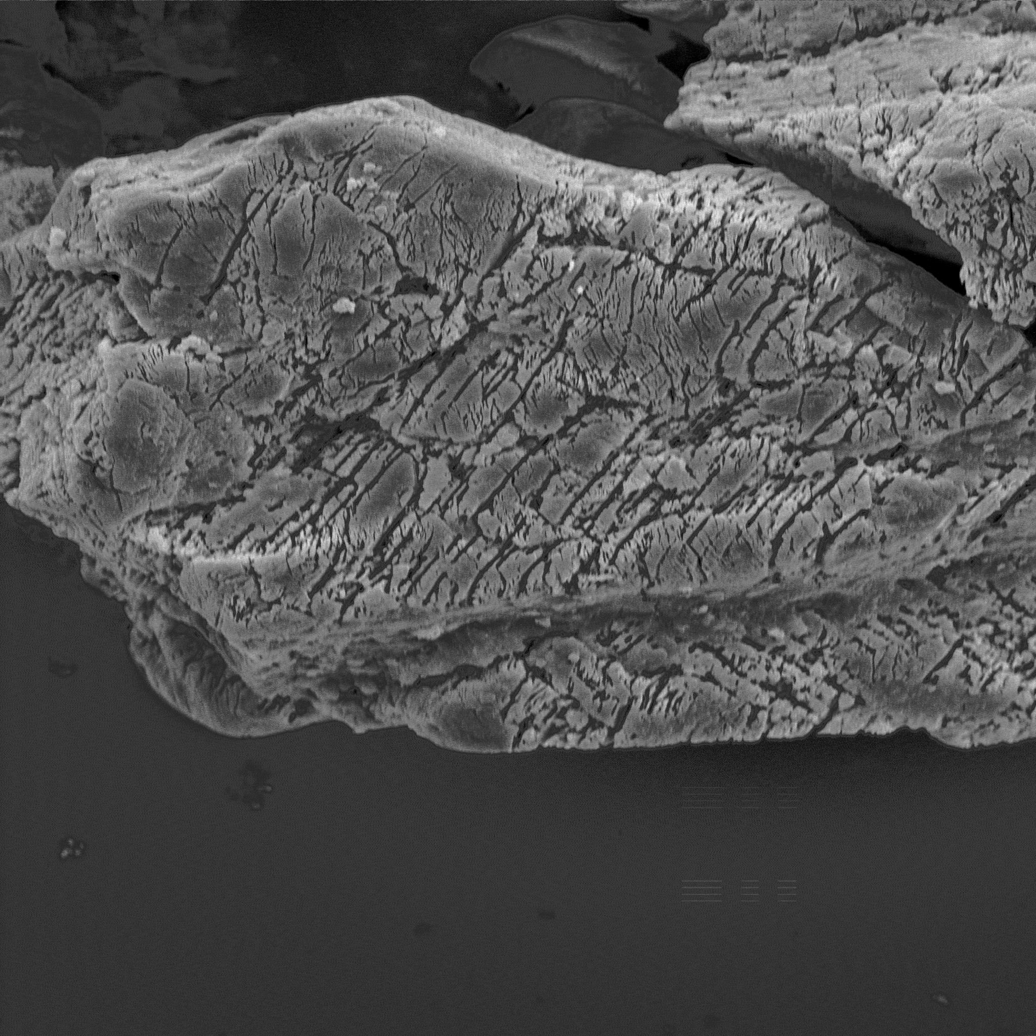
A shocked grain of quartz under the SEM. You can see the multiple fractures where the quartz was turned to glass (in the impact) and then removed with HF. Sample from a core depth of 2,295.5 feet.
Isolation and HF dissolution by Dr. Don Triplehorn, SEM image by Ray R. Collins.
ß The first (left) of the three length-key lines is 10 mircons long.
Note the 2 planes of parallel lines; shock features often exhibit more than one plane because the mineral lattice has more than one plane of weak bonds which will break down to glass as the shock wave passes through the crystal.
Shocked grains of quartz under the SEM. You can see the multiple fractures where the quartz was turned to glass (in the impact) and then removed with HF acid. Multiple directions of shock is observed. Sample from a core depth of 2,295.5 feet.
Isolation and HF dissolution by Dr. Don Triplehorn, SEM image by Ray R. Collins.
ß The first (left) of the three length-key lines is 10 microns long.
Are there other shock features we can find? Diamonds have been reported to form during the very high temperatures and pressures of impact, if the target material has enough carbon in it. While looking for zircons, Dr. Triplehorn discovered what appeared to be a diamond. Under a light microscope it had a high refractive index, a slightly yellowish color and an interesting crystal shape. This appeared to be very similar to a diamond crystal (albeit a very tiny one). Is it a diamond? Was it a result of impact, or did it perhaps originate from the drill bit used to drill the core?
Drill bits use crushed diamond powder (Mull). Though diamond crystals might be found in the powder this is unlikely. But to help rule out this possibility we can look for wear on the crystal faces. We also need to identify the crystal as diamond.
Possible diamond crystal found in the core of Avak meteor structure. Sample from a core depth of 2,037 feet.
Isolated by Dr. Don Triplehorn, SEM image by Ray R. Collins
ß The first (left) of the three length-key lines is 10 microns long.
Diamonds are almost entirely carbon, with some occasional very minor impurities (which give diamonds color). Unfortunately carbon can not be detected by the SEM. I did a scan to determine the chemical makeup of the crystal, but did not find anything but gold (which is expected, since the diamond was coated with gold prior to putting it in the SEM).
This lack of data indicates, however, that this is almost surely a diamond, for there are few elements the SEM will detect almost anything that form crystals like this.
Now, the real question is: can this technique be used to identify a previously unidentified impact structure? As a preliminary investigation I took some silt from the bottom of Sithylemenkat Lake in the spring of 1998. This spring (1999) I had a look at my sample with the SEM.
Possible quartz grain from the floor of Sithylemenkat Lake. Sample was primarily silt and clay, with a large amount of organic material. Sample taken from the side of the large hot spring in the spring of 1998. Water depth 30 feet; bottom surface silt.
SEM image by Ray R. Collins
ß The first (left) of the two length-key lines is 1 micron long.
This sample was not dissolved in HF. Thus, even if shock patterns were present, they would not be visible. More work needs to be done with the Sithylemenkat samples to determine if they were subjected to shock. However the technique for imaging shock with the SEM has now been demonstrated, so it should be possible to move ahead with the investigation of Sithylemenkat Lake as an impact structure using the SEM.
Many thanks to Dr. Don Triplehorn for his assistance in providing the samples to scan, and most especially the quartz samples that had been dipped in HF.
Collins, Florence R.(*) 1961, Core test and test wells, Barrow area, Alaska: U.S. Geological Survey Professional Paper 305-K, p. 569-644.
French, Bevan M. 1998, Traces of Catastrophe: A Handbook of Shock-Metamorphic Effects in Terrestrial Meteorite Impact Structures. LPI Contribution No. 954, Lunar and Planetary Institute, Houston.
Mull, Gill. Personal conversation, 4/21/99.
*Author's mother.
The current copyright laws protect this page, even though not specifically copyrighted.
However if you want to use portions of it feel free to do so, though I would appreciate it if you would acknowledge my authorship.
This page written spring 1999.